From Severity Arguments to Evidence - Based Decisions:
How UKBIC Built a Repeatable DFMEA Capability in 12 Weeks.
"We went from arguments about severity ratings to confident, evidence-based decisions using a formula-based SC/CC classification system."
Client Overview
CompanyUK Battery Industrialisation Centre
 LocationUK
 IndustryBattery Research & Pilot Facility
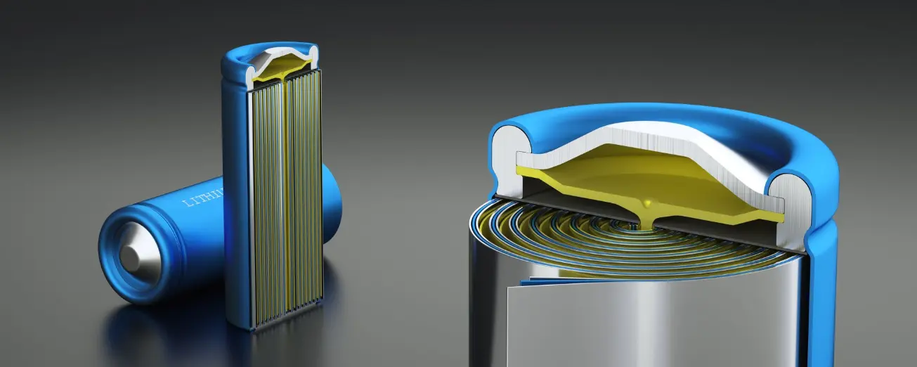
EquipmentLithium-ion Battery Development
REsults
The Challenge
The UK Battery Industrialisation Centre (UKBIC) in Coventry is at the forefront of scaling battery cell manufacturing for the UK's electrification ambitions. Their technology team was talented but lacked the tools, structure and repeatable methodology needed for Design Failure Mode and Effects Analysis (DFMEA).
Through initial scoping workshops, seven distinct barriers emerged — each captured directly through workshops with the team:
DFMEA perceived as too complex and time-consuming — engineers avoid it or treat it as a tick-box exercise because sessions are unstructured and overwhelming.
Scope creep and no defined completion criteria — without clear boundaries, sessions expand endlessly with no measurable endpoint.
Blurred lines between DFMEA and PFMEA — design risk sessions routinely drift into process failure modes, wasting time and creating confusion.
Inconsistent scoring of Severity, Occurrence and Detection — different engineers rate identical failure modes differently, undermining confidence in risk priorities.
No agreed SC/CC classification methodology — design, quality and manufacturing teams cannot agree on Special and Critical Characteristic definitions, stalling decisions.
Workshops that produce discussion but no outputs — without facilitation discipline, sessions become unproductive conversations with no tangible deliverables.
Critical knowledge locked in individuals — experienced engineers hold failure mode expertise that is never documented, structured or made transferable
With automotive OEMs demanding IATF 16949 compliance and the EU Battery Regulation introducing new traceability requirements, the business needed to move fast — but move right.
Our Approach
What We Were Tasked To Do
UKBIC defined success across three dimensions:
- Resolving historic challenges
- Building current capability
- Enabling future potential
Success Criteria:
 "Generic DFMEA that is easy to understand, with links to DVP"
"Relevant controls identified, not just SCs & CCs"
"UKBIC team have knowledge, competency & tool to progress DFMEA"
"SC & CC justification to wider business, and lead DFMEA with customers"
"Becomes easy to navigate and part of day-to-day activities"
Future Potential Targets:
"UKBIC team can lead workshops with customers to manage their tech & product development risk"
"Anticipate potential faults in customer products" — proactive risk identification as a service offering
"Tool to manage + boost yield, can be presented to customers" — DFMEA as a commercial differentiator
"Roll out to the PFMEA" — design risk methodology extending into process risk management
"Live value-added document process which facilitates training & robust design"
Our Approach:
Deep Stakeholder Engagement: We conducted extensive workshops and interviews with stakeholders across the different functions of the technology team —from senior management and program leads to process engineers and production managers. This allowed us to understand the distinct pain points and requirements of each function.
Technical & Design Deep Dives: The team analysed all technical specification and documentations of the existing 21700 design, to understand potential design risks.
How We Delivered
We believe that true transformation comes from integrating people, processes, and technology, all underpinned by good data. We embedded within UKBIC's technology team for a 12-week intensive programme, combining VDA/AIAG 2019 methodology with hands-on delivery in Relyence FMEA software.
Phase 1 - Foundation: APQP/PPAP & NPI Framework
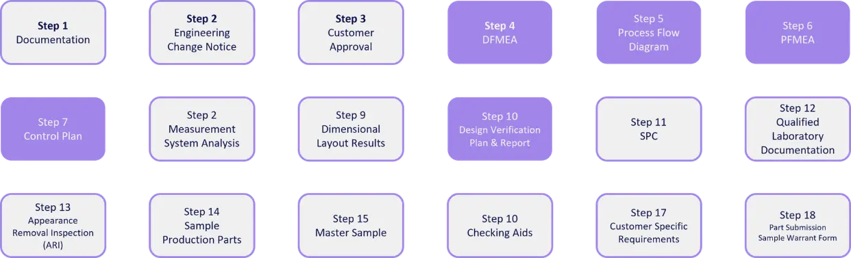
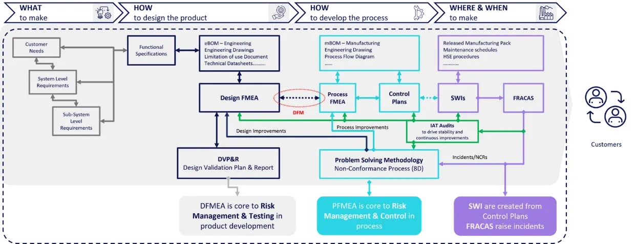
We established the end-to-end process framework before touching a single failure mode. Built the NPI process linking Requirements → Product Development → Process Development → Build Management. Mapped DFMEA into APQP's 5-phase structure and aligned all 18 PPAP steps — connecting DFMEA (Step 4) to Process Flow Diagrams, PFMEA and Control Plans.
PPAP Overview
NPI Process Overview
Phase 2 - Scoping & Structural Analysis
We began with a comprehensive structural decomposition of the battery cell’s engineering Bill of Materials (eBOM) across all sub-assemblies, to accurately capture the breakdown of key components. Clear component breakdown helps with identifying failure modes and ensures risks are addressed effectively.
AIAG / VDA 2019 DFMEA Process Steps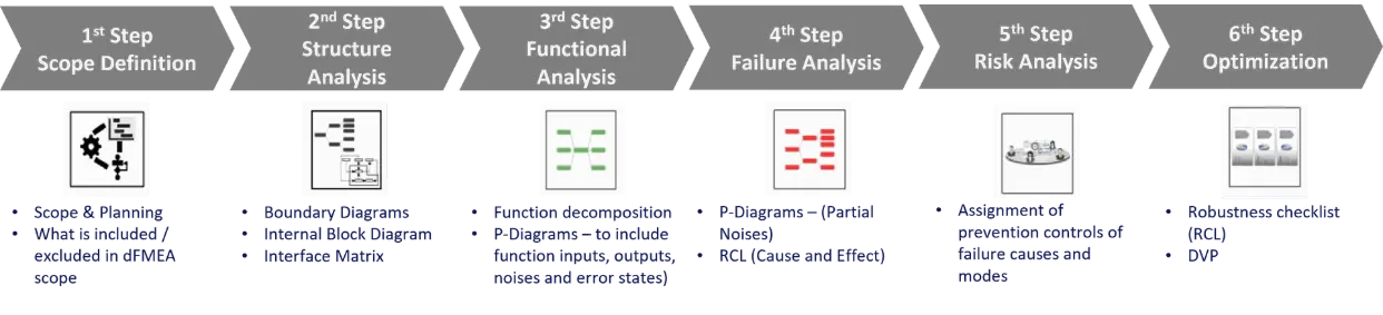
Phase 3 — Boundary Diagrams & P-Diagrams
We analysed every sub-assembly identify potential failure pathways and system interactions, developing detailed boundary diagrams for each component to track energy transfers, interface flows, and the impact of external influences. This was supplemented by the use of parameter diagrams (P-Diagrams) to categorise signal and control factors against environmental noise and error states. Finally, interface matrices were utilised to document the complex relationships existing both within individual sub-assemblies and across the entire battery cell.
Phase 4 — Failure Analysis & Risk Scoring
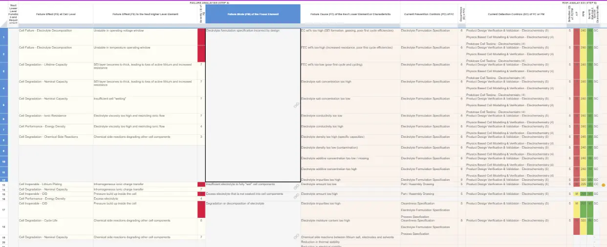
We conducted a series of cross-functional workshops to ensure the risk analysis was both structured and repeatable. The assessment followed the end-to-end 7-step VDA/AIAG 2019 methodology, which established a consistent 'auto-flow' — linking effects to modes and causes across the entire system hierarchy. To categorise risk, we applied a formula-based approach for identifying Critical and Significant Characteristics: any mode with a Severity score of 9 or 10 was classified as a Critical Characteristic (CC), while those with a Severity above 6 and an Occurrence above 4 were designated as Significant Characteristics (SC). Finally, we integrated a product-level Failure Effects column to provide the necessary context to sharpen our definitions of specific failure modes and their root causes.
Phase 5 — DVP&R Integration & Optimisation
We ensured full design-to-test traceability and established a direct connection between identified risks and the project’s validation plans. Each DFMEA entry was linked to specific DVP&R (Design Verification Plan and Report) worksheets using evidence pointers to streamline verification. We further strengthened this framework by mapping prevention controls directly to engineering specifications and drawings, while detection controls were aligned with specific testing protocols. To evaluate these risks from multiple perspectives, Action Priority (AP), Risk Priority Number (RPN), and Severity/Hazard (SH) scoring was used, which provided a comprehensive set of lenses for risk management.
Phase 6 — Knowledge Transfer & Capability Building
The primary objective of the project was to establish long-term self-sufficiency within the internal team. To support this, we developed generic DFMEA blueprints designed for seamless reuse across future battery cell programs. The engineering team underwent rigorous training on the Relyence platform and VDA/AIAG methodologies, including the practical application of Boundary and P-diagrams. This was supported by a comprehensive suite of training materials covering APQP, PPAP, and NPI fundamentals. To ensure these skills were fully internalized, we conducted over 200 hours of facilitated workshops; these were not theoretical classroom sessions, but live DFMEA exercises performed on actual battery cell products where real engineering decisions were made in real-time.
Results & Impact
12 Weeks
DELIVERED ON TIME
15+
WORKSHOPS
90%
IMRPOVMENT IN RISK SCORING
5
ENGINEERS FULLY TRAINED
Key Achievements
Full eBOM Analysis: structural decomposition across all battery cell sub-assemblies including phantom items for Anode & Cathode formulation and coating processesBoundary diagrams: created for every sub-assembly capturing energy transfers, interface flows and external environment influencesP-diagrams: developed identifying signal factors, control factors, noise factors and all four error state categories (no function, partial function, intermittent function, over function)Formula-based: SC/CC classification system, which removes guess work in the Severity, Occurence & Detection scoringFailure Analysis: auto-flow implemented in Relyence FMEA software — Failure Effects flow up to Failure Modes at next higher level, Failure Modes flow up to Failure Causes at next higher levelDVP&R (Design Validation Plan & Report): worksheets linked directly to DFMEA risk items for full design-to-test traceabilityStructured DFMEA Process: NPI process framework established linking Requirements → Product Development → Process Development → Build ManagementBaseline FMEA for future Customers: "Generic" DFMEA blueprints created for reuse across different cell formats and customer programTraining & Skill Development: Team competency transferred — UKBIC engineers now independently lead DFMEA workshops with their own customers
"The structured approach to scoring and the boundary diagrams transformed how our team thinks about design risk. We went from arguments about severity ratings to confident, evidence-based decisions using a formula-based SC/CC classification system."